First presented at the Altshuller Institute TRIZCON2000, May 1, 2000
By Dr. Larry Zeidner and Dr. Ralph Wood
The Collaborative Innovation (CI) process has been developed at United Technologies Research Center (UTRC) as an integrated collection of best-practice design methods (including TRIZ), enhanced and simplified to support Integrated Product Development (IPD) teams during conceptual design. Over the past 3 years, CI has been applied to a wide range of UTC innovation efforts, from cost-reduction of mature products to clean-sheet design of new types of products & processes. The CI process enables an IPD team to: a) focus their innovation efforts on opportunities that have the greatest potential of adding stakeholder value, b) use stakeholder value to guide concept evaluation and selection, and c) create a development plan that will reduce risk as quickly as possible.
CI is focused on conceptual design because it has long been clear that at least 70% of the cost, reliability, performance, safety, etc. of products are set during conceptual design. Conceptual design is the highest-leverage opportunity for innovation.
Conceptual design teams routinely struggle with 3 issues:
· Innovation effort can be focused on many different aspects of a product and its related processes. Conceptual design teams need to know where to focus their innovation efforts, strategically, to add the most value. Innovation for innovation's sake alone is not valuable.
· Unlike detailed design, conceptual design lacks detailed prototypes that can be "test-driven" by representative customers or subjected to instrumented testing. During conceptual design, teams typically consider between 10-100 rough-hewn concepts. It is impractical to either confront representative customers with, or test models of all of these concepts. Instead, the team needs a "value-based gauge" that it can use to evaluate and select concepts based on their potential to add stakeholder value.
· Once concepts have been selected, value can only be added if they are pursued; action is required. A pre-requisite to action is a development plan and a clear business case to proceed. There is risk inherent in product development, so decisions are made under conditions of uncertainty and the result is rework. Time and cost for rework can be substantially reduced by development plans that reduce risk as quickly as possible, so that decisions are made under conditions of greater certainty. Conceptual design teams need methods to create development plans that reduce risk as early as possible in the development cycle.
Detailed design involves optimization and determining precise values of design parameters; conceptual design involves consideration of alternative product and process architectures and technological approaches. While bounding ranges for numerical design parameters may be assumed, specific numerical values are as yet unknown. Consequently, conceptual design teams demand quick, simple methods, that are faster and less complex than detailed analyses and detailed requirements definition. They are unwilling to commit the time and effort required to apply detailed methods, since their information is in such rough form. For this reason, many methods that are best practices during detailed design must be simplified for concept design without losing their kernel of effectiveness.
Integrated Product Development (IPD) core teams are ideally composed of and supported by individuals having radically different backgrounds and areas of expertise. It is this diversity that brings a variety of perspectives to conceptual design and increases the likelihood that multiple design alternatives will be generated and evaluated and that life-cycle issues will be considered systemically, rather than as afterthoughts and engineering changes. But many of these diverse individuals are not experts on all facets of the existing product and its related life-cycle processes. They must be provided with appropriate documentation to enable them to understand and contribute to the conceptual design discussion. Available product and process documents are typically suitable for detailed design, involving considerable implementation detail that obscures the fundamental architecture of the product and related processes. Very often, the detailed design documents do not even address the primary conceptual design issues. Conceptual design teams need product/process architectural documentation, without the distraction of detailed-design issues.
This article introduces the Collaborative Innovation (CI) process and its steps for concept design. Each step is explained along with the methods used.
During the past 3 years, CI has been developed and used to support conceptual design teams within UTC's Business Units, including Pratt & Whitney (jet engines), Otis Elevator (elevator systems), and International Fuel Cells (power-generation systems). These teams' missions ranged from innovative conceptual redesigns for cost reduction of mature products to radically innovative designs of new types of products.
CI sets the stage for innovation by enabling the members of IPD teams, and those who support them, to rapidly engage and contribute, so that they readily add value through the diversity of their backgrounds and skills. CI accomplishes this by modeling the functional architecture of a product and its associated processes so that this information is accessible to the core team and those who support it.
CI explicitly captures the team's assumptions and decisions so that others in the organization can consider them and add value by identifying necessary adjustments and/or by embracing them based on clear understanding. This is accomplished openly, during frequent reviews, and privately, as individuals draw their own conclusions by examining explicit team documentation.
CI leads to action by presenting a clear business case for its proposed concepts, along with a logically organized wealth of supporting information so that individual assumptions and decisions can be readily substantiated.
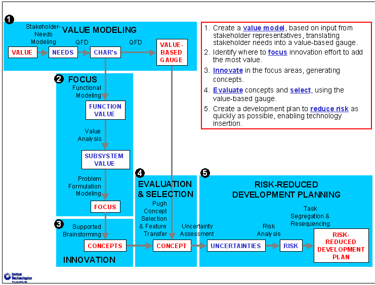
Figure
1: CI Process Steps
CI consists of the 5 steps shown in Figure 1:
1. Value Modeling: Create a weighted stakeholder-value model. Based on input from stakeholder representatives, translate stakeholder needs into a value-based gauge that can be used to evaluate and select concepts.
2. Innovation Focus: Identify where to focus innovation effort to add the most value for stakeholders.
3. Innovation: Innovate in the focus areas, generating a wide variety of concepts that span the design space, minimizing the risk of being "blind-sided" by competitors' products and processes.
4. Concept Evaluation & Selection: Evaluate concepts, using the value-based gauge, and select those that can add the most value for stakeholders.
5. Risk-Reduced Development Planning (RRDP): Create a development plan to reduce risk as quickly as possible, reducing cost and time for rework.

Figure
2: Using the "Value-Based Gauge" for Value Modeling
The principle of value modeling is illustrated in Figure 2. If the team had an understanding of the relative value of a set of tangible, measurable characteristics of the product or process, and could take a proposed concept and place a gauge against it to measure its score on each characteristic, they would have a good idea of its value. They could readily determine the value of each of its characteristics and thus its total value.
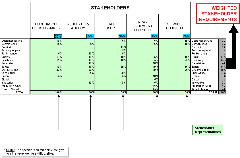
Figure
3: Stakeholder-Needs Modeling
Value Modeling consists of:
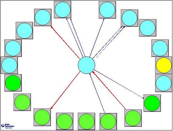
· Stakeholder-Needs Modeling:
Relevant stakeholder* categories are identified (Figure 3). A short list of the stakeholders' top-level needs is developed. The best available stakeholder representatives are consulted to determine the importance of each need to each category of stakeholder. The stakeholder representatives also provide input to the IPD team's decision on the relative importance that each category of stakeholder's perspective will have on the design. A weighted average of these two types of input represents the combined stakeholder value associated with each need.
· Simplified QFD
Quality-Function Deployment (QFD) [Hauser 88] or "House of Quality" is a well-known best practice to understand the relationship between customer needs and ways of satisfying those needs. Elaborate QFD methods have been applied for a wide range of applications, often involving a sequential multi-tiered "waterfall" approach.
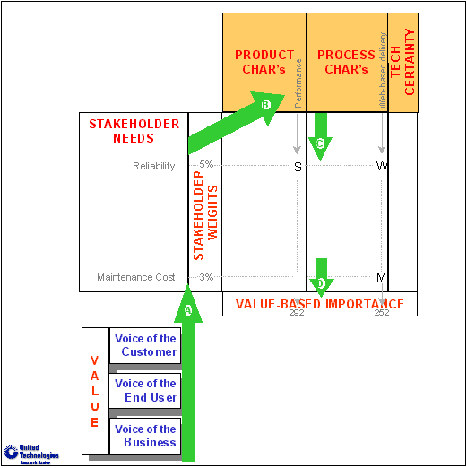
Figure
4: Simplified QFD
Figure 4 shows how Simplified QFD is used within CI. A short list of tangible characteristics of the product or process being designed and of related life-cycle processes is created. Each characteristic is believed to be important toward satisfying stakeholder needs and must be able to be assessed for proposed concepts before they have been implemented. The characteristics should be as independent of one another as possible, to avoid double counting. A weighted average of the stakeholder-need weights and the importance weights for the characteristics results in an overall rating of the importance of each characteristic toward providing value. This set of key characteristics, together with their relative weights, is the "Value-Based Gauge" that is later used to evaluate and select concepts.
The primary benefits of Simplified QFD are:
· Its use of only one QFD table: enhanced QFD methods use many cascaded tables, which consume substantial time and therefore limit their usefulness upfront in conceptual design.
· Its concurrency: both product and process characteristics are evaluated simultaneously.
· Its inclusion of "technical certainty" as a standard characteristic to assess the sensitivity of stakeholders to new technology that is not yet "tried and true" in this specific application.
· It combines requirements of all relevant stakeholders, rather than only the Voice of the Customer.
· It identifies contradictions that can be resolved using the TRIZ principles [Altshuller 84].
History has shown the disadvantages of focusing innovation where it is technically easiest or where it is most “interesting” or technically challenging. Products and processes that have resulted from such misguided innovation have not generally been successful unless they also happened to add sufficient value.
Focusing innovation based on the actions of market leaders is disadvantageous because only the effect of their design efforts is visible, e.g., the results of their intellectual property (IP) strategy and their first preliminary product offerings. The IP strategy and product and process knowledge that produced these artifacts is not only hidden, but typically one design-cycle old. Focusing solely on these artifacts is likely to perpetuate a market-following position.
A healthier strategy is to evaluate the design space, quickly assessing each area to determine
its potential value, its value with current technology in the current marketplace, and the technology hurdles and market factors that must be overcome to yield its potential. This allows a design team to drill down in areas of the design space that present the most valuable innovation opportunities while understanding and managing the risk that competitors might pursue other areas. This strategy limits competitive risk and enables the business to react with agility when new technologies or market changes present opportunities.

Figure
5: Problem-Formulation (PF) Modeling
Innovation Focus consists of:
· Problem-Formulation (PF) Modeling:
Problem-Formulation [Terninko 98] is a well-known TRIZ method. Figure 5 illustrates Problem-Formulation (PF) modeling as it is used within CI.
The problem-formulation model documents the rationale behind the existing (baseline) product or process design. Modeling begins with identification of the few Principal Useful Functions (PUFs). These are the primary reasons for the product or process’s existence. Next the Useful Functions (UFs), required to provide the PUFs, are modeled. (At this point, the problem-formulation model is essentially equivalent to a standard Functional Analysis Structured Technique (FAST) [Creasy 73] model (commonly used in Value Engineering).
Next, the Harmful Functions (HFs) and Principal Harmful Functions (PHFs), caused by these Useful Functions (Ufs), are modeled. While HFs are disadvantageous, they are not typically obvious or directly problematic to the user. PHFs are more serious than HFs and are typically obvious and problematic to the user. Finally, the UFs, used to mitigate the HFs, are modeled.
Figure
6: The structure of an actual Problem-Formulation (PF) Model (textual
descriptors omitted)
Figure 6 shows an example of an actual problem formulation model (the descriptors have been omitted to protect proprietary information). Note that there is a band of PUFs at the top, which this system must perform. Below them is a band of UFs, which are the current design’s approach to performing the PUFs. Below them is a horizontal band of HFs and PHFs, which are caused by the current design’s approach to performing the PUFs. Below them is a band of mitigating UFs, which are useful, but which are only there to solve the problems caused by the current design’s approach to performing the PUFs. Finally, at the bottom of the PF diagram there is a band of HFs and PHFs caused by the mitigation. In this case it is system cost and complexity which feeds back to cause other HFs. In other cases HFs result from requirements on weight, volume, noise, vibration or parasitic losses.
Figure
7: Functional Modeling (FM)
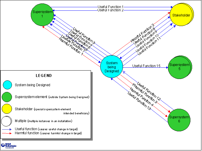
· Functional Modeling (FM):
Functional modeling is a well-known method of understanding which system elements perform which useful and harmful functions. It is a common element in TRIZ analysis, although it takes different forms with different authors. Figures 7 illustrates Functional Modeling (FM) as it is used within CI.
The notation for functional modeling involves blue circles representing elements of the system being designed, green circles representing elements of the "outersystem" (i.e., elements outside the system being designed), and yellow circles representing the stakeholders: outersystem elements that are the primary beneficiaries of the system being designed. (Note that for sub-systems, the stakeholders in a functional model are typically other sub-systems, as opposed to the human stakeholders considered in Value Modeling.)
The functions are represented as arrows between elements. Useful functions are shown in blue and harmful functions in red. A function between two elements indicates that the origin element performs the function and consequently changes or limits an attribute of the destination element. This is analogous to the information in OAF tables, in Ford's USIT methodology [Sickafus 97], except that USIT acknowledges not only one, but two origin elements causing the function (as does the theory of Triads [Kowalick 98]). USIT also explicitly models the attributes of the two origin objects that cause the function to occur, as well as the attribute of the destination object.

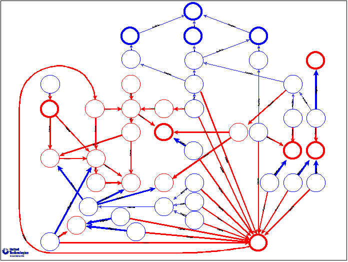
Figure
8: An actual one-level Functional Model (textual descriptors omitted)
Figure
9: One page of an actual multi-level Functional Model (textual descriptors
omitted)
Figures 8 and 9 show pieces of two different actual functional models in different formats (the descriptors have been omitted to protect proprietary information). Figure 8 shows a complete one-level FM. Figure 9 shows one page of a multi-level FM, in which each element is diagrammed at the center of its own page, showing all of the functional interactions it has with other elements. This approach shows the context, within which each element exists, along with its functional interfaces to that environment. This multi-level modeling is performed using a hierarchical, object-oriented network modeling tool that preserves network integrity, so that all views of the model that involve any particular link show it identically, with all of its relevant graphical and textual attribute information.

Figure
10: Value Analysis (VA)
· Value Analysis (VA):
Value analysis is the part of CI's innovation focus step that actually identifies where to focus to add value. Value engineering defines the Value of a design as its Functionality (its benefits) divided by its Problems and its Costs [Miles 61]. Figure 10 illustrates how Value Analysis is performed in CI. Functionality is plotted against the sum of Problems and Cost. Functionality includes contribution to PUFs, but does NOT include mitigating UFs. An ideal system element (shown in green) would provide excellent functionality with no problems or costs, while a worthless and harmful system element (shown in red) would provide no functionality but cause significant problems at high cost.
The system elements from the Functional Model are graphed based on their functionality, problems and cost. The diagonal lines are lines of constant value. The horizontal line indicates no value, the 22-degree line represents more value, the 39-degree line represents even more value, etc. So on this graph, element A is of extremely low value, while element B is of extremely high value. Note that cost-reduction teams are purely focused on moving the elements to the left on the VA graph (or eliminating them). Radical Product-Innovation Teams (clean-sheet designs and radical derivatives) are concerned primarily with moving the elements upward on the VA graph, adding substantial new functionality to them (in some cases, by satisfying previously unknown stakeholder needs). These teams may also reduce cost if possible.
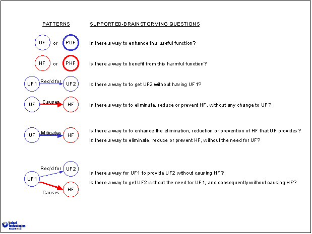
Figure
11: PF
model patterns and associated supported-brainstorming facilitation questions
As shown in Figure 11, from the Problem-Formulation model, there is a small set of possible patterns of useful and harmful functions, each of which corresponds to a logical question that should be asked to determine if there’s a better possible design. [Terninko 98] These questions are automatically generated from the PF model. The supported brainstorming process is facilitated using these questions in an order based on their height in the PF model (top to bottom) and proceeds down the branches of the PF model that the Value Analysis indicated were the best opportunities to add value. Since the questions are extremely open-ended for the purpose of facilitation, it is possible to generate questions that are one step less open, in that they pursue a particular conceptual line of change. There are many established sources of these conceptual lines of change, including the TRIZ principles [Altshuller 98], the USIT solution strategies [Sickafus 97], the Lateral Thinking techniques [De Bono 90], and "Thinkertoys" [Michalko 91].
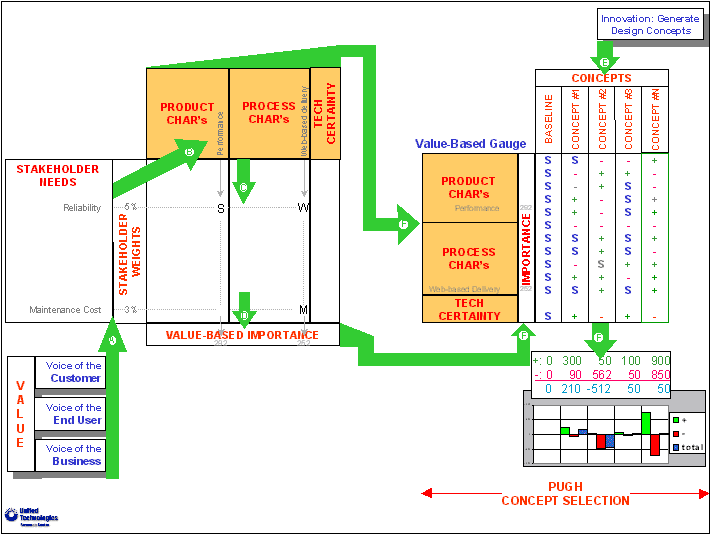
Figure
12: Pugh Concept Selection
As shown in Figure 12, CI uses “Pugh Concept Selection” [Pugh 91] to evaluate concepts and compare them against a common baseline concept. The Value-Based Gauge created as the result of Value Modeling is used as the weighted selection criteria. Pugh Concept Selection evaluates each system-level concept against a common baseline, which is either the current product design, or a surrogate (the same system that was used as the baseline for PF modeling and for Functional Modeling). For each concept, each product or process characteristic is assessed in comparison with the baseline design. The concept either performs better ("+") with respect to this characteristic than the baseline, the same ("S"), or worse ("-"). As a result, Pugh produces 3 values for each concept:
· how beneficial the concept is, vs. the value of the baseline (the sum of the weights of characteristics scoring "+"),
· how deficient the concept is, vs. the value of the baseline (the sum of the weights of characteristics scoring "-"), and
· the total value of the concept, vs. the value of the baseline (the sum of the weights of characteristics scoring "+" minus the sum of the weights of characteristics scoring "-").
Note that the total doesn’t tell the whole story. For example, two concepts could have the same total, while one has excellent advantages along with terrible deficiencies, while the other could just have a few modest advantages and deficiencies. All 3 values are presented and the team's judgement is used to interpret the results.
Since Pugh Concept Selection compares all concepts against a baseline, it minimizes the number of comparisons that must be considered, as compared with methods such as "paired comparisons." [Kaufman 89] Since CI provides a direct computational chain, linking stakeholder needs weighting, QFD, and Pugh Concept Selection, validating the QFD and the concept evaluations is easy. Scenarios are used to establish extreme points at which they provide selections that agree with the team's perception. If a scenario doesn't provide sensible selections, the relevant portions of the evaluations and then the QFD are examined to determine whether the team's perceptions, the QFD or the evaluations are at fault. This quickly flushes out evaluation inconsistencies. Since the QFD is meant to explicitly capture the understanding of the team, if it yields results with which the team disagrees, then it is immediately clear where better information or clarification is required. Typical scenarios that can be usefully explored to validate the QFD and the concept evaluations are alternate markets, future markets, and "gut-feel" weightings. Once the QFD and the evaluations have been validated in this fashion, the individual stakeholder-need weightings can be validated by considering them individually and in meaningful groupings as the weights on the rows of the QFD.
Pugh Concept Selection also makes it easy to identify which features of different concepts should be combined to yield higher-value hybrid concepts.
Once one or more concepts have been selected, the conceptual-design team must create a development plan so that the investment decision, to develop the concept, can be weighed against competing alternative investments (based on metrics such as ROI, NPV, expected value). Technology development and product development both involve considerable risk. Risk is defined as the product of uncertainty of failure and the associated severity of failure. Risk is reduced by either reducing uncertainty, by gathering information or conducting tests or analyses, or by reducing the severity of failure, by increasing the expected value of "fallback" or contingency plans.
It is clear that if risk can be reduced earlier within development, then decisions can be made with greater certainty, and consequently less rework will be necessary. Less rework means shorter time to market and reduced development cost. Risk-Reduced Development Planning is a combination of risk-management best practices [Duncan 96] that a team can use to create a development plan that reduces risk as quickly as possible.
A common problem during the development of product systems arises due to insufficient communication between sub-system organizational groups. When fallback plans are planned without sufficient communication, it is common that some of the sub-system fallback plans have unforeseen complications elsewhere in the system and are thus infeasible. A design team can improve the management of risk by planning system-wide fallback plans explicitly, so that their system-wide viability is assured.
A plan that identifies when risk will be reduced can be used to reduce time-to-market in another way. Passport ("stage-gate" or "tollgate") reviews can be scheduled to occur soon after significant risk reduction steps have occurred, to minimize the delay from the moment that information is gained to the moment that it is used to decide how to proceed. This delay is wasted time and should be minimized.
Risk-Reduced Development Planning consists of:
· Uncertainty Assessment:
The primary uncertainty issues are identified and assessed based on their likelihood of failure. For each uncertainty issue, the likelihood of failure is comprised of four probabilities that are based on assessment of technology-readiness gaps that routinely lead product development programs to failure. For each uncertainty issue, these gaps assess its intellectual difficulty, the definition and stability of its requirements, the ability to measure its success, and the availability and capability of resources for it.

Figure
13: Evaluation of a risk portfolio along with the initial risk-reduction
plan.
· Risk analysis:
As shown in Figure 13, an initial development plan is formulated and the resulting risk portfolio is considered, along with the change in that risk portfolio that would result, if the plan were executed.
Risk involves three additional factors: "time criticality" (when the uncertainty is reduced), dependencies between uncertainties, and severity of adopting fallback plans.
Time criticality is a factor affecting uncertainty. It is the mean time, during the span of the relevant portion of the development program, at which the uncertainty is actually reduced. Clearly, if test results show, during the last day of the program, that the fallback plan must be adopted, then there is no choice -- time and budget are both exhausted. However, if test results yield the same result during the first days of the program, there are many options -- people are creative and there is plenty of time and budget to find viable alternatives. The later uncertainty is reduced, the higher the effective uncertainty and, consequently, the risk of failure. Time criticality is a multiplying factor that rises exponentially in time to penalize the late resolution of uncertainty.
Dependencies between uncertainties can either increase or decrease their effective uncertainty. When some uncertainty issues adopt their fallback plans, others automatically adopt their fallback plans, regardless of how well they were proceeding. For example, if feasibility of design of a new power supply is one uncertainty issue for a system, and feasibility of design of a multiplexing power-distribution system is another, then fallback to the existing power supply would force abandonment of the new power-distribution system, even if it was actually feasible. On the other hand, when some uncertainty issues adopt their fallback plans, other uncertainty issues are much more likely to succeed. For example, feasibility of design of the system's thermal-management may be assured to succeed once fallback to the existing power supply occurs.
For each uncertainty issue, the severity of adopting its fallback plan is the remaining element of risk. Severity indicates the loss of stakeholder value involved in adopting the fallback plan. This is the only element of value that is involved in risk. It can be assessed using either the weighted stakeholder needs or the value-based gauge.
· Task segregation and re-sequencing:
The overall development plan is considered, and uncertainty-reducing development tasks are segregated from high-certainty “turn-the-crank” tasks. The entire product-development effort is re-sequenced to first complete the uncertainty-reduction tasks and then, once risk has been substantially reduced, to pursue the high-certainty tasks.
While there are some novel adaptations of best practices in the Collaborative Innovation (CI) process, its novelty is largely its integration and simplification of these best practice methods into a streamlined, repeatable process that can be taught, facilitated and used regularly to drive innovation and stimulate rapid business decision-making.
[Altshuller 84] Altshuller, G.S., Creativity as an Exact Science, Gordon & Breach Science Publishing House, 1984.
[Altshuller 98] Altshuller, G., 40 Principles: TRIZ Keys to Technical Innovation, with drawings by Uri Fedoseev, and additional material by Lev Shulyak. Technical Innovation Center, 1998.
[Creasy 73] Creasy, R., Functional Analysis System Technique Manual, Society of American Value Engineers, 1973.
[De Bono 90] De Bono, E.,Lateral Thinking: Creativity Step-By-Step, Harper Collins, 1990.
[Duncan 96] Duncan, W., A Guide to the Project Management Body of Knowledge, Project Management Institute, 1996. (http://www.pmi.org/)
[Hauser 88] Hauser, J. R. and D. Clausing (1988). "The House of Quality," The Harvard Business Review, May-June, No. 3, pp 63-73.
[Kaufman 89] Kaufman, J., Value Engineering for the Practitioner, North Carolina State Univ, 1989.
[Kowalick 98] Kowalick, James, "Triads: Their Relationship to TRIZ," TRIZ Journal, June 1998.
[Michalko 91] Michalko, M., Thinkertoys (A Handbook of Business Creativity), Ten Speed Press, 1991.
[Miles 61] Miles, L. D., Techniques of Value Analysis and Engineering, McGraw-Hill, 1961.
[Pugh 91] Pugh, S., Total design : integrated methods for successful product engineering , Addison-Wesley, 1991.
[Sickafus 97] Sickafus, E. Unified Structured Inventive Thinking: How to Invent, Ntelleck, 1997.
[Terninko 98] Terninko, J., Zusman, A., and Zlotin, B., Systematic Innovation : An Introduction to TRIZ (Theory of Inventive Problem Solving), Saint Lucie Press, 1998.
Dr. Larry Zeidner leads the Advanced Design Methods (ADM) group at United Technologies Research Center (UTRC). His research involves innovation management, value modeling, functional analysis, supported brainstorming, knowledge management, and risk analysis. Before joining UTRC, Larry was a member of the faculty in Boston University's Manufacturing Engineering Department, where his research and teaching included automatic generation of code to drive NC machines for custom "art to part" manufacturing systems, graphically programmed cooperative asynchronous hardware/software systems, and advanced graphical user interfaces. Larry earned his PhD in Civil Engineering in 1983 and his BSE in Electrical Engineering and Computer Science in 1980, from Princeton University.
Dr. Ralph T. Wood is Director of Enterprise Productivity, UTC Corporate Quality. For 5 years prior to this assignment, he led the Product Development and Manufacturing Department and then the Management of Technology Department at the United Technologies Research Center. From 1990 to 1994 he was the Associate Director of DARPA's Concurrent Engineering Research Center at West Virginia University and a consultant on product development to industry. Ralph spent the majority of his career at GE, starting at Knolls Atomic Power Laboratory, where he was a lead methods development engineer working on naval nuclear reactors, and ending at GE's Corporate Research and Development Center, where he conducted R&D programs in energy conversion, two-phase flow, nuclear reactor containment, process modeling, industrial lasers, intelligent processing of materials, and concurrent engineering. Ralph holds ScB, ScM, and PhD degrees in mechanical engineering from Brown University. He is co-author of three US Patents and numerous journal articles.
* Stakeholders are those affected by the product or process design, and whose perspective is considered important (typically due to influence on the purchasing decision). Typical stakeholders include customers (divided into relevant market segments), regulatory agencies, and organizations within the value chain (e.g., new-product design & manufacturing, maintenance, repair & overhaul).