| PICTURE 1: Standing Stubble | PICTURE 2: Soil Diagram |
 |
 |
First published in the Proceedings of TRIZCON2002, The Altshuller Institute, April 2002
Comparing Results of Functional Modeling Methods for Agricultural Process and Implement Development Problems
Joe A. Miller, M.S.
Quality Process Consulting, Lake Zurich, IL USA
Ellen Domb, Ph.D.
PQR Group, Upland, CA USA
ABSTRACT
Two methods of modeling a system's functionality are widely used in TRIZ applications for problem solving, system simplification, and improvement. Both these methods are distinct from classical Substance Field (Su-Field) modeling. (Ref. 1) Subject - Action (verb) - Object models are based on very specific tangible physical components of a system and the explicit (physical) effects they exert on other components of the system. "Operational" models, generally known as "problem formulator" models, allow broader definition of a system's elements to include actions as well as components. These models focus on whether those elements ultimately contribute Useful or Harmful effects to the primary purpose of the system or elements supporting that purpose. (Ref. 2)
An additional modeling approach, Causal Loop models derived from the Systems Thinking discipline, may also serve the TRIZ practioner by helping to identify those system elements and /or actions in a system that are most pertinent to causing a desired change in performance.
The results of applying these three functional modeling and analysis methods to several modern agricultural problems will be presented. The process example addresses cropping procedures and potential education programs for farming, while the implement example involves product design issues.
THE CASE STUDY
Air Seeding in No-Till Farming
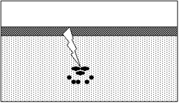
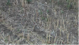
No-till agriculture differs from conventional farm practices by leaving the soil undisturbed after the harvest. (Picture 1 of standing stubble.) In the spring, seed is planted directly in the un-disturbed field, and is protected by the duff from the previous crop. (Picture 2.)
| PICTURE 1: Standing Stubble | PICTURE 2: Soil Diagram |
|
|
|
No-till agriculture is good because it keeps water and CO2 in the soil, reduces the amount of fertilizer needed, reduces the amount of fuel used to process the fields, reduces labor of farmers, and reduces wear and tear on the machinery. No-till farming is now done on almost 20% of U. S. farmland and may be even more in Canada. (Refs. 3, 4)
But, No-till requires specialized tools to plant the seeds, place the fertilizer, and condition the soil for germination and growth. (See web sites, Refs. 5, 6)
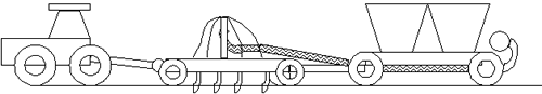
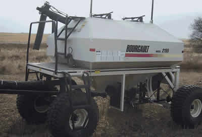
A common device to perform combined seeding and fertilizer application is the air seeder. The principles of operation of the air seeder are quite simple: Seed and / or fertilizer are carried by air through tubes and dropped into an opening in the ground. In practice, the devices become quite complex.
PICTURE 3: Complete Air Seeder System Diagram|
|
||
|
Tractor |
Frame |
Cart |
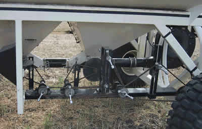
A frame, to be pulled by a tractor, has folding �wings� to allow transport and storage. The frame has multiple tired wheels to carry its weight. Dimensions vary among models, but may be 30 to 50 feet wide. The frame may also carry one or more bins. The frame carries seed and fertilizer distribution tubing, and provides for the mounting of multiple soil openers and multiple specialized roller wheels to pack the soil after delivery.
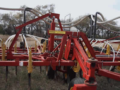
PICTURE 4: Frame showing Air Tubing and Openers
Seed and fertilizer bins are carried on a separate cart. The cart has tired wheels to carry its weight and to obtain motive power for the mechanisms carried on the cart. The wheels provide driving force for multiple sets of adjustable sprocket drive systems which meter materials out of the bins and into a complex of distribution tubing. Air is blown through the distribution tubing to carry the seed and fertilizer. At points where the material being delivered is required to divide into multiple pathways, the air supply tubes are fitted with flat impingement plates, with numerous smaller tubes providing exit pathways.
PICTURE 5: Cart with bins and undercarriage
The small tubes eventually bring the materials to multiple soil openers. These are mounted on the frame with penetration depth adjustments and with a retraction mechanism for transport between fields. A typical air seeder may carry 40 to 60 or more openers. Openers are removable / replaceable, and several types are available.
PICTURE 6: Typical Opener and Packing Wheels

Design of these agricultural tools is evolving rapidly. This would be a �fertile� area for a technology evolution/TRIZ problem solving study-you can easily see the progression from point to line to area to volume tools, from simple mechanisms to highly flexible mechanisms, from muscle power to mechanical power to pneumatic/hydraulic systems.
But, these are highly complex, extremely expensive systems that can be set up to do one thing very well, but may take a lot of time to reconfigure to do something else, such as using a different ratio of seed to fertilizer, or changing the separation of seed and fertilizer, etc. Changes in field conditions occur frequently, over short distance, and optimum seed/fertilizer relationships should change to match the field conditions for maximum harvest. (Ref. 7)
PICTURE 7: Sprocket and Chain System for Control of Seed and Fertilizer Application Rates / Ratios.
For the purpose of testing three function modeling methods, we will limit the discussion to the improvement of the speed of changing only one of these parameters. Changing the ratio of seed and fertilizer is the primary problem that will be used for this example, but both problems are of great interest in the no-till farming equipment industry.
THE SYSTEM MODELS
Conventional TRIZ Functional Modeling Analysis
The same No-till Airseeding situation is described below using each of the modeling systems. A �formulator� model for air seeding is shown in Figure 1. This method is described in Ref. 8 and has been popularized by Ideation International�s Ideation Workbench � software. Each box represents either a useful or harmful function, and the arrows between boxes show relationships-one function can cause or prevent another. A large number of potential problem statements are generated from this model by substitution in general formulas such as the following:
The TRIZ practioner has to examine the list of potential problem statements, select the ones that are most appropriate for the situation, and then re-express them in terms of the language of the situation in order to begin solving the problem.
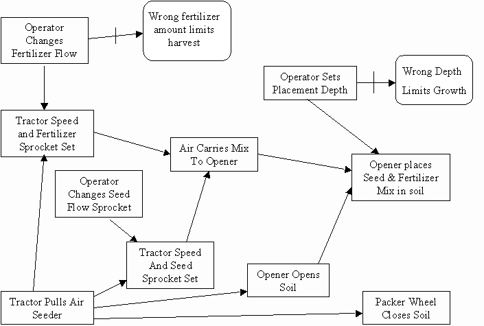
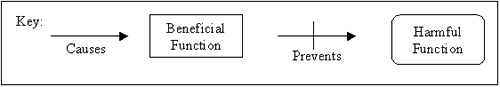
Figure 1. The formulator model of the airseeder.
Diagram of the model for the airseeder, using the format of the problem formulator method, showing functions and links between functions.The function analysis model is based on system engineering methods of defining a function in terms of two objects and the action that one performs on the other. (Ref. 9) The graphical form of function analysis has been popularized in TRIZ through Invention Machine Co.�s TechOptimizer� as shown in Fig. 2. This method is now also used in CREAX�s CreaTRIZ� Software. Solid arrows indicate useful functions, dashed arrows indicate useful functions that are not operating at their best value (either too much or too little) and wavy arrows indicate harmful functions. Problem statements are developed directly from the graphics by examination, for example:
Problem statements are also developed through the process of trimming, such as
Finally, problem statements are developed by applying a list of generic problem statements, based on the 76 standard solutions (Ref. 10) to the function statement.
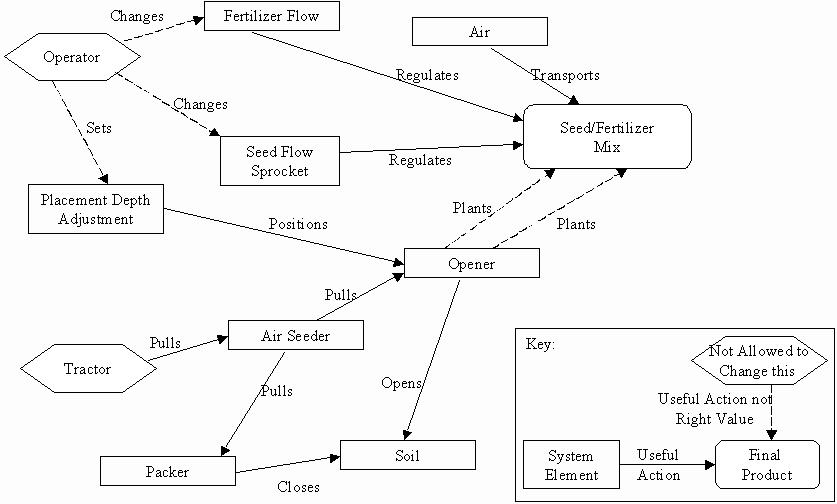
Figure 2. Function analysis model diagram of the airseeder. A function is shown as two components and a linking action. Functions can be useful or harmful, and useful functions can be adequate or not. In this model, there are no harmful functions, but there are several that are not at
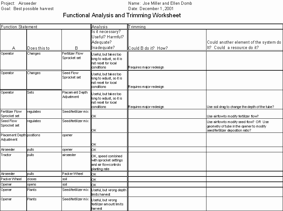
the right values (usually called �inadequate�).Using a Tabular Function Analysis Model (FA Worksheet from Practical Innovation class)
An alternative or supplementary method is the use of a table, as shown in Table 1. The problem statements are constructed in the same way as in the graphical model of the function analysis. Some people find the compact summary form of the table easier to use.
Table 1. Function Analysis and Trimming for Problem Identification Using a Table.
Using the Causal Loop modeling system
The causal loop model is shown in Figure 3a. This methodology is based on the Systems Thinking Discipline developed and popularized by Peter Senge. (Refs. 11, 12) One automated version of this modeling method, the I-Think Software by High Performance Systems, is described in Reference 13, and is among several software products available (Ref 14). The modeling method utilizes a nouns and verbs representation of the elements of a system. Nouns, represented by rectangles, are amounts, quantities, accumulations, things, states of being, or levels, etc. The verbs are activities that cause change, either positive or negative, in the magnitude of the nouns. Verbs are shown as directional pipes or flows, with regulators. (Ref. 15)
Three additional graphic elements are useful in representing causal link model elements. First is the cloud, which can serve as an infinite source or sink for the noun elements. This allows models to be bounded for practicality, and allows a focus on sub-systems of particular interest. The second additional element is an action connector, shown as a solid curvilinear arrowed line, to show causal linkages, inputs or outputs, between model elements.
The final graphic element is a converter, or circle. Converters serve to input parametric values, to link or combine information, and to modify flows.
Figure 3a. Causal Loop Model of Airseeder Operation.
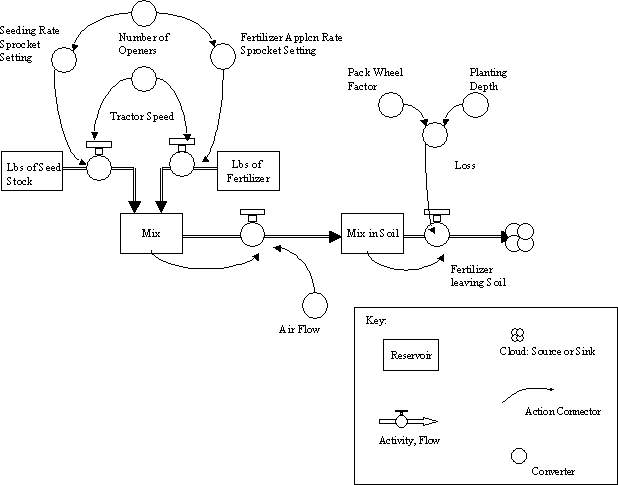
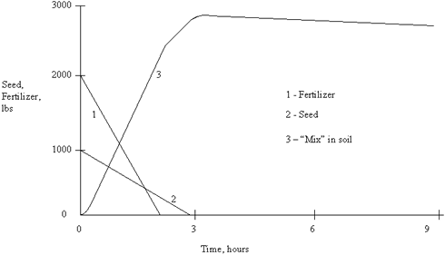
Figure 3b. Graphic output of Airseeder modeling.
Analysis
All three models gave the same suggestions for the problems to be solved to improve the airseeder, but the models required the user to take significantly different pathways to develop that set of tasks or suggestions.
Specifically, for the function analysis model, problem statements involving use of the supersystem came only from repeated use of trimming. If the user did not try trimming repeatedly for each new development of the model, he might not see the opportunities for solving the problem using the supersystem. Combining the function analysis model with the use of the system operator (9 Windows) (Ref. 16) would overcome this problem, although it would add somewhat to the complexity of using the function analysis model. The formulator model made these solutions very visible, but very abstract.
The use of resources is a very powerful TRIZ technique. Both the graphical function analysis model and the formulator model only generate tasks for the resources that are explicitly named in the model. Resources that are idle in the initial conditions of the problem are not specifically suggested for tasks, except in the table form of function analysis and in the detailed suggestions section of the formulator model.
Causal Loop models make it very clear that time dimension must be considered and that the nature of the problem may be different in different episodes. Time is considered as part of the zone of conflict analysis in classical TRIZ, but is not explicitly treated in any of the function analysis approaches. One Time span of interest is when things are flowing out of storage, mixing, going into the ground. Another time span of interest (level of system interest) is the ensemble of openers being pulled across the field, and the field being seeded at the right density and right depth. This is a 9 Windows issue-component, supersystem and system all produce different questions.
Causal loop modeling helps find harmful issues (what goes out of control when?). It also lets you explore the nature and intensity of interactions. For example, the system may need an alarm or a stop when either fertilizer or seed runs out. The mechanisms may not be very necessary now with fixed settings, but would be more needed with an automated or self-adjusting system, since predictability of running out is lower.
For experienced users, any �suggestion� by one system was also in the �suggestions� from the other, BUT the paths were very different, and the inspection/accept/reject process might have not gotten you there.
The three modeling systems are distinctly different in dealing with the parameters of the functions being modeled. In descending order of detail, they are as follows:
Table 2. Comparison of three pathways to deciding to develop a control system other than the operator-controlled fertilizer flow sprocket set.
| Formulator | Function Analysis | Causal Loop |
| Directly from the graphical model. The suggestions �Find a way to improve �operator changes fertilizer flow sprocket set�� and �Find a way to prevent �wrong fertilizer amount limits harvest� without �operator changes fertilizer flow sprocket set�� both offer solution pathways | Directly from the graphical or table model. Dashed blue line shows that something needs to be improved, and parameter table show that it is the speed of changing the device. Trimming operator and trimming fertilizer flow sprocket set suggest 2 different solution pathways | Examination of the diagram shows that the operator is the source of the delay in making the changes, which could lead the farmer to continue work without making the changes. Examination of the deposition rate charts show how much time is saved vs. how much crop is lost, to help decide on the amount to be spent on improvement. |
Table 3. Comparison of three pathways to deciding that we should develop an opener that makes it possible to deposit the seed and fertilizer in separate locations or at separate times.
| Formulator | Function Analysis | Causal Loop |
| Directly from the existing model. High level suggestion �Consider transitioning to the next generation of the system that will provide [the] (Opener places Seed & Fertilizer mix in soil) in a more effective way and/or will be free of existing problems,� This is further detailed with specific suggestions to consider improving Ideality of the opener system, transforming the existing system into bi- or poly-systems, segmenting or restructuring the existing system, increasing dynamism or controllability of the existing system that provides the Opener places Seed & Fertilizer mix in soil. | Directly from both the graphical and the table model. The tabular model explicitly states that �wrong fertilizer amount limits harvest,� and asks if �another element of the system could do it?�, or if a resource could do it. Likewise, the graphical model suggests �increasing the ratio� of seed and fertilizer mix. While this does not explicitly address delivering the materials separately, this would be a logical extension for a skilled analyst. | Examination of the diagram shows that there is no (obvious) functionality in the system to place seed and fertilizer separately from each other. However, the functionality of depositing a mix is demonstrated, and by inspection, the model could be expanded to parallel sub-systems (bi- or poly- systems) based on the same distribution functionality, but without mixing. Additionally, an implicit suggestion for improving the system could come from asking if the seed-fertilizer combination could be �un-mixed� at / in the opener, and the two components directed separately with resource elements (air, for example) already in the system. |
Comparison issues for further discussion
Is Causal Loop modeling more like an animated Su-field model? The focus of Causal Loop modeling is on identifying what are the opportunities for improvement and for control, and then evaluating the effectiveness of those approaches. Likewise, the Su-field is a way of recording a judgment. It reminds us to look at tool, object, energy, transmission, and guidance in a system to see if they are all there and working.
Formulator and Function Analysis are less structured, more preliminary explorations of the situation environment. They provide for an initial recognition of interactions and forced categorization of functionality as useful, harmful, etc.
It appears that TRIZ functional modeling, with any of these tools, is somewhat holographic in nature. If we create a model of part of a system of interest to us, and utilize that model to explore ways to improve Ideality, we may see suggested tasks or pathways of improvement that lead us outside the part we have modeled. They may really address another part of the system or even the super-system.
A potential application pathway for these tools might well be to first do either a Formulator or Function Model analysis, then develop an animated Causal Loop Model for interface with design or process development teams, and finally to create Su-Field models of the specific elements of interest in the system.
All of these modeling systems offer expandability. Given the ability to incorporate time, either explicitly or implicitly, we could expand these models to include seed and fertilizer procurement and delivery sub-systems, or additional tractor and airseeder functionality.
In addition, these model systems are all amenable to �drilling down� through greater detail of the entire model or a particular sub-system for either focus or for added analysis of more specific functionality. The operational characteristics and physical components of the openers, for example, is an area of significant technical development and evolution. On-going design efforts here might be aided by TRIZ functional analysis.
For the No-till case study system, another reasonable expansion of the scope of the model might be to include the soil (both the physics and chemistry) as a more detailed sub-system. We might also model the growth characteristics of the plants, their genetics and nutrient requirements / responses.
A special case of model expansion is the ability to combine models of different systems into a more complete model of a supersystem. An example would be the combination of a model of the Flax residual straw case described above with the airseeder model. Since the Flax straw if left on the ground could become an impediment to proper opening of the ground during No-till planting, a complete analysis might yield unexpected approaches to broader system improvement. Preliminary formulator analysis of the standalone Flax residue problem identified several approaches to system improvement. A specific embodiment of one of those approaches is now in evaluation.
CONCLUSIONS
Professor T. Ohfuji (Ref. 17), among others, has observed that product and / or process functions are tasks which we have delegated to machines. Feature sets are designed into machines to bring functions about. We are using the FA and formulator models as �machines� to do the function of analysis but these diagrams are static, and have forced us, in order to not see a static system, to animate them in our imagination, and with our existing knowledge. We do �mental� simulations in our heads when we see each box, each function, and see the time of operation. Each graphic based system provides a framework for our mental processing. The Causal Loop model does the processing for us, in a limited but repeatable version. The Causal Loop modeling approach may help us observe and recognize system functionality that we have not previously been aware of. It may also cause us to realize the time dependency of many functions on each other.
A big benefit (no news here-many people have remarked on it) of any functional modeling is that a project team creating the diagram together (any diagram) are forced to document their understanding of the problem, and go do root cause analysis (or go back to data gathering, or, or, or, �) if they can�t agree on the nature of the functions or interactions. The depth and breadth of understanding necessary for good design, or good problem solving, may require or be aided by, the creation of multiple models. Using more that one different modeling techniques may well be very cost effective, in today�s complex and time compressed technical world.
Conclusion about inspection/sorting vs. creation of problem statements in terms of maturity of TRIZ system.
The tools and techniques we use in TRIZ are still immature. Per Professor T. Ohfuji�s observation, we have delegated the function of identifying problems and / or improvements to our analytical devices, but they do not work fully or flawlessly. We have set (some of) these devices to give us lists of possible actions, but we must still use our intellect and experience to decide which of these are not nonsense by a process of inspection and sorting. We must also still �animate� these models, either mentally or with computer simulation, and judge the results against our experience base. Mature modeling systems will perhaps be more powerful in their ability to highlight areas where performance is inadequate, where a system is most sensitive to improved control, and where system simplification may lead toward increased ideality. We hope these comments are helpful in furthering the maturity of our discipline.
REFERENCES
|
�
Copyright 1997-2005 CTQ Media LLC |