Dr. Tim Clapp
Professor, NCSU
Dr. Michael Slocum
Adjunct Assistant Professor, NCSU
Slocum1946@aol.com
Abstract
Presented are the TRIZ methodologies and results of using these tools on a graduate research topic concerning the properties of a particle filled fiber. A problem arose from drawing these particle filled fibers. The main focus of the student was to employ the ARIZ algorithm to develop highly innovative solutions. At least one innovative solution is generated. A variant of this same solution has been employed successfully in the liquid crystal industry.Introduction
The first question one might ask is why even add particles to a polymer. Rigid particles can improve some of the properties of the bulk polymer. Modulus, resistance to creep, and fracture toughness are all improved. Also the coefficient of thermal expansion is lowered. My research work and specific problem deal with the modulus properties of a particle filled polypropylene fiber. In particular the problem centers on the reduction of modulus of a drawn filled fiber when compared to an undrawn filled fiber.
Our composite fiber consisted of two main phases, polypropylene matrix and particulate wollastonite filler. The particle filler wollastonite is a needle shaped mineral crystal. The wollastonite looks like a fine white powder to the naked eye. Our fiber forming process begins by mixing these two phases. The mixing takes place in an Atlas mixing extruder. Small amounts of polymer chips and particle powder are alternately poured into the hopper located on the mixer. The amount of particle added depends on the volume fraction desired for the final composite fiber. The polymer melts around the particle as the composite rod is extruded from the mixer. This rod is then chipped and ground into a coarse powder. This powder is then returned to the hopper located on the mixer. The coarse powder is then extruded once again to improve the distribution of the particle in the polymer. The rod extruded from this second mixing is then chipped and ground into a coarse powder. This powder is then extruded into a fiber using the Bradford melt extruder. The fiber exits the spinneret and drops approximately three feet into a water bath to quench the fibers. From the water bath the fiber is wound onto a cardboard tube using a winding machine. These fibers are then hand drawn at 80° C. The drawing strengthens the polymer by orienting the molecular chains in the direction of the long fiber axis. Drawing should also orient our needle shaped particles more closely to the long fiber axis. Without drawing the fibers are brittle which makes them hard to handle or prepare for testing.
Problem Description
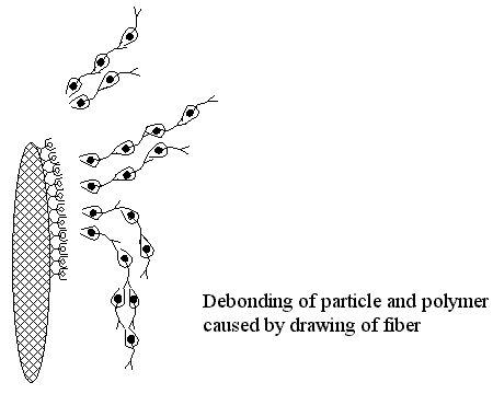
The effect we attained from drawing was completely opposite from what we had hypothesized. Therefore the strengthening effects cause by drawing may not apply directly to particle filled systems. After testing samples of the drawn and undrawn fibers with the same volume fraction an unexpected result was observed. When compared to the undrawn samples the drawn samples had a lower modulus. We believe this is due to the generation of voids in the fiber during drawing. As the fiber is drawn the polymer is pulled away from the particle causing a debonding of the particle from the polymer. In effect a hole is created in the fiber, which leads to a decrease in modulus. How can we orient the polymer molecular chains and not debond the particle?
How Can TRIZ Help?
Hopefully by using TRIZ I can reduce if not prevent psychological inertia, identify and resolve contradictions instead of compromising, and develop higher level innovative solutions. With such a complex problem I decided that ARIZ would be the best place to start. Also ARIZ seemed to be the best way to employ all of the TRIZ tools systematically and hopefully generate ideas at each step in the process.
ARIZ
The first step is mini-problem formulation. A description of the problem in generic terms will be formed. This step should identify the useful and harmful functions, tools and products. Contradictions should begin to be elucidated. This process begins with finding the Key Problem, debonding the particle during drawing. Therefore energy is the Useful Function Tool and moving the polymer molecular chains is the Useful Function Product. The Harmful Function Tool is also energy, which separates the particle from the polymer, Harmful Function Product. If this energy is large the molecules are moved but the particles are separated from the polymer. If this energy is small the particles are not separated from the polymer but the polymer molecular chains are not moved either. Herein lies the initial contradiction; the energy needs to be both large and small. Therefore it is essential under minimum changes to the system to move molecules without separating particles from the polymer.
The next step involves trying to solve this contradiction discovered in the first step. Since the contradiction is a physical contradiction one can use the Separation Principles: separation in time, space, upon condition, and within a whole and its parts. Applying Separation in Time reveals our first glimpse of solutions.
Applying Separation in Upon Condition gave me the following ideas.
Already at this early point in ARIZ we begin to get solutions. We also see how useful the Separation Principles are when applied to physical contradictions. The physical contradiction can also be transformed into a technical contradiction. This is why the similarity was pointed out in the solutions listed above.
In the next step the conflict is enforced and extrapolated to extremes. If very large energy is applied the particle is separated and floats free from the polymer. If even more energy is applied maybe just to the particle we arrive at an idea very similar to those above. The particle could move fast enough to generate heat from friction cause between the particle and polymer. At the other extreme if a very small energy is applied the particles are not separated. However a solution may lie in applying the small energy with periodic action which is principle 19. Apply a frequency of energy like a small periodic drawing force. This force should over time orient the molecules of the polymer. The movement of the molecules should be slow enough to allow the particle to also slowly move with the polymer and thereby prevent the rapid debonding seen in our original process.
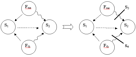
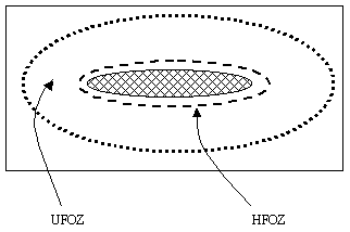
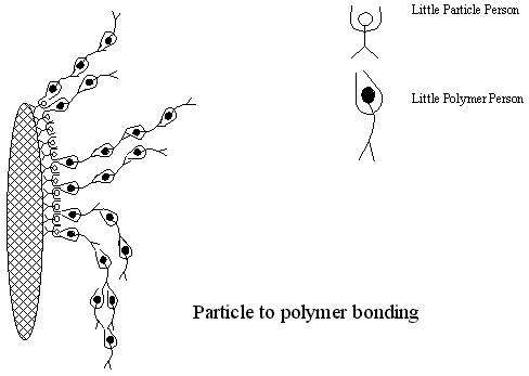
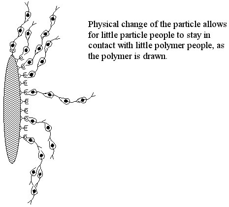
The next few steps of the ARIZ algorithm are designed to allow the problem solver to focus on the resources available or resources needed for solutions. These resources could take the form of fields or objects. For my system it is essential to introduce some resource X which prevents the separation of the particle from the polymer and does not prevent the molecules of the polymer from moving during drawing. Often times it is helpful to sketch the system using Substance Field Modeling. These diagrams allow the problem solver to identify the fields and substance present in their system. Once this knowledge is obtained one can decided if their system is complete. These diagrams also allow one to see the desired, insufficient, and harmful interactions between forces and substances in the system. If we diagram our system during drawing we find it contains two forces. There is a mechanical force from the drawing action and a thermal force applied by drawing at 80° C. The two substances are the molecules of the polymer and the particle. This situation gives us a combined Su-Field model. The mechanical and thermal forces have a harmful interaction with the particle. These same forces have a desired effect with the molecules of the polymer. The mechanical and thermal forces also lead to an insufficient interaction between the polymer and the particle (see appendix B). To correct these interactions we need to introduce some substances to block or modify the interactions into desired interactions. A substance that would increase the interaction between the particle and the polymer could possibly block the effect of the two fields on the particle. Something like a coupling agent or a surface treatment could increase the chemical bond energy greater than the energies of the two fields. Another visual tool that is useful for analyzing the system is Operational Zone Analysis. The operational zone can be broken down into the Harmful Function Operation Zone and The Useful Function Operational Zone. The HFOZ of my system contains the particle and the interface between the particle and the polymer. The UFOZ contains the molecules of the polymer. These two zones overlap where the molecules of the polymer enter the interface between the polymer and the particle (see appendix C). This overlap zone can be further broken down Using Smart Little Persons Modeling. The current system contains two types of people, particle and polymer people. The particle people are rigid on the surface of the particle. The polymer people form a chain by holding onto each other’s feet. At one end of this chain the polymer people hold onto the particle people (see appendix D). When a force is applied that moves the polymer people their grip to the particle people is broken. Therefore the ideal situation would be the polymer people move without letting go of the particle people. Or conversely the particle people could be free to move on the surface of the particle while the polymer molecules are moving. This would be the case if the particle where a fluid. The fluid state would allow the particle people to absorb the energy by moving; therefore, the energy is not concentrated on the rigid bond between the particle and polymer.
Possible Solution
Fluid Particle
During drawing the molecules of the polymer move and orient with the mechanical force of drawing. Some of these polymer molecules are bonded to a fluid particle that has been distributed in the polymer. As the molecules of the polymer move the particle molecules on the surface of the particle attached to them are also free to move. In this case the bond between the particle and the polymer is not stressed to the same degree as with the rigid particle. Now once orientation of the polymer molecules is attained the particles can be solidified to obtained the desired rigid particle. Radiation like ultraviolet radiation is used to cross-link and solidify polymer matrices. If a liquid crystal particle is used the particle can be oriented with a weak field and solidified under these orientation conditions. This liquid crystal technology is used with polymer dispersed liquid crystal display devices. Small droplets of liquid crystal are dispersed in the polymer. The molecules of these droplets orient with a weak electric or magnetic field allowing light to pass through the panel. This particle orientation also has an added benefit. An increased load bearing capability in the direction of the orientation is achieved.
Appendix A
Resources| Substances | Forces | Time |
| Polypropylene Wollastonite | Thermal Mechanical Pressure Gravity | In mixer |
| Molecules | Chemical bond | In water bath |
| Coefficient of thermal expansion | Friction | Exposed to air |
| Density | To drop to water bath | |
| Chipper | Drawing | |
| Winder | ||
| Cardboard tube | ||
| Glass transition temperature | ||
| Melting temperature | ||
| Crystallinity | ||
| Particle size | ||
| Amount of particle | ||
| Amount of polypropylene | ||
| Humidity | ||
| Void around particle | ||
| Spinneret diameter | ||
| Spinneret shape | ||
| Diameter of the fiber | ||
| Particle shape | ||
| Length of fiber | ||
| Electrical conduction | ||
| Thermal conduction | ||
| Solubility | ||
| Air | ||
| Water | ||
| Speed | ||
| Atlas mixing extruder | ||
| Bradford extruder | ||
| Grinder | ||

References
Salamatov, Yuri. TRIZ: The Right Solution at the Right Time, A Guide to Innovative Problem Solving. Insytec B.V., Netherlands. 1998.
Terninko, John., Zusman, Alla., and Zlotin, Boris. Step-by-Step TRIZ: Creating Innovative Solution Concepts. Responsible Management, New Hampshire. 1996.
Ahmed, S. and Jones, F.R. A Review of Particulate Reinforcement Theories for Polymer Composites. Journal of Materials Science, 25 (1990) 4933-4942.