Most if not all engineering systems experience a strength versus weight conflict of some description. The contradiction most commonly manifests itself in the balance designers attempt to strike between the need to ensure adequate strength, and the parallel desire to utilise the minimum amount of material, and thus achieve the lowest cost.
The strength/weight conflict plays a particularly important role in the design of bridges. In order to remain competitive in the bridge engineering sector, designers are forced into a perpetual drive to achieve bridge designs which use less materials than their predecessors.
Historical evidence firmly suggests that, using traditional design approaches, this quest for ever better strength/weight ratios – coupled with other factors - inevitably leads to some kind of catastrophic failure:-
|
Bridge |
Type |
Probable Failure Mechanism |
Year |
Interval |
|
Dee |
Trussed Girder |
Torsional Instability |
1847 |
- |
|
Tay |
Truss |
Unstable in wind |
1879 |
32 |
|
Quebec |
Cantilever |
Compressive buckling |
1907 |
28 |
|
Tacoma Narrows |
Suspension |
Aerodynamic instability |
1940 |
33 |
|
Milford Haven |
Box Girder |
Plate Buckling |
1970 |
30 |
|
? |
Cable-Stayed ? |
Instability ? |
c2000 |
c30 |
Source: Sibley & Walker, ‘Structural Accidents and Their Causes’, I CivE, 1977
Table 1: Landmark Bridge Failures
TRIZ offers much to both help understand the mechanisms underlying the bridge failure trend, and – more importantly – offers tools to help designers continue to innovate new design solutions which improve strength/weight ratios without compromising the structural integrity of the bridge.
This article examines some of the issues surrounding famous historical bridge failures and shows how they may begin to be explained in the context of the TRIZ problem definition and problem solving process.
Probably the most widely reported – and thus most famous – bridge failure of all time, the 1940 failure of the Tacoma Narrows suspension bridge (Figure 1), represents a classic case of the consequences of pushing a design too far. The failure is extremely well documented in this context in Reference 1.
|
The history of suspension bridges before and around the time of the Tacoma Narrows failure is revealing in the context of the drive by designer’s to produce designs of ever increasing span. The main driver of course was to reduce the amount of time, material and thus cost of the bridge. As in all prudent design, bridge material requirements were calculated on the basis of strength calculations onto which significant factors of safety were added. As experience in the design of suspension bridges grew, these safety factors were driven downwards in order to reduce material usage. History shows, that the factors are edged downwards and downwards until failure occurred:-
| Bridge | Span (ft) | Failure date |
| Dryburgh Abbey (UK) | 260 | 1818 |
| Union (UK) | 449 | 1821 |
| Menai Straits (UK) | 580 | 1839 |
| Roche Bernard (France) | 641 | 1852 |
| Wheeling (US) | 1010 | 1854 |
| Niagara-Lewiston (US-Canada) | 1041 | 1864 |
| Niagara-Clifton (US-Canada) | 1260 | 1889 |
| Tacoma Narrows (US) | 2800 | 1940 |
Following each incident, again as in all good design, the experiences of one failure influenced the design of successive bridges – usually prompting a modification in design style and an increase in safety factor levels. Then, as experience with the new design style increased, the safety factors were gradually reduced again… until the next failure occurred. And so on.
The Reference 1 evidence firmly suggests that the Tacoma Narrows Bridge failure occurred because the particular style employed in the design exceeded the fundamental limits of the strength-weight contradiction of the particular design style. More specifically, the failure occurred because the design rules used were incomplete. This same phenomenon is present in all the failures detailed in Table 1.
 |
The process described by the figure sees the designer first calculating the required strength of a bridge. The designer then adds a safety factor to take into account of uncertainties. As experience grows, subsequent designers – seeing that an earlier design has not failed – are encouraged to reduce safety factors in order to reduce material usage. This process repeats until a failure occurs. In retrospect, it is then determined that the failure occurred because the ACTUAL strength required was higher than the CALCULATED strength required. The difference between the two values usually emerges because of an effect which was either considered to be secondary or was not considered at all during the formulation of the original strength calculation rules.
In the case of the Tacoma Narrows failure the missing effect was the passage of wind over the bridge. Failure to take account of this effect meant that the bridge had insufficient torsional strength.
In evolutionary terms, the Tacoma Narrow Bridge design style had exceeded the limits of its fundamental strength versus weight capability.
Subsequent suspension bridge designs in which there was a desire to increase span length beyond the 2600ft of Tacoma Narrows, required a change in the design paradigm.
In TRIZ terms, the Tacoma Narrows Bridge encountered an administrative contradiction between the demand for spanning greater gaps with less material, and the fundamental ability of the design style to meet the demand (NB this definition of the administrative contradiction differs from several other definitions – see Footnote). TRIZ findings show that progress beyond this limit demands a change in paradigm. A good example of this as far as suspension bridges are concerned is the Akashi Kaikyo Bridge, linking the islands of Honshu and Shikoku in Japan (Figure 3), which has a centre section span of over 6500ft. Stability is maintained in this structure through incorporation of pendulum-like devices on the towers to keep them from swaying and a stabilizing fin beneath the centre deck to resist high winds
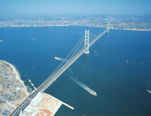 |
(In terms of the Contradiction Matrix, it is perhaps interesting to note here that with the Technical Contradiction between the desire to improve the weight of the bridge and worsening effect this has on the stability, leads to ‘Periodic Action’ as one of the recommended Inventive Principles. This is very encouraging in light of the fact that the idea of a pendulum is probably not an instinctive response to the bridge stability problem.)
Cable-Stayed Bridge Designs
 |
As with the suspension bridge, the evolution of the cable-stayed design style also exhibits a growing demand for greater and greater strength/weight ratios. A graph showing the historical trend towards longer span lengths is illustrated in Figure 5.
The prediction made by Sibley and Walker in the Table 1 list of bridge failures that the evolution of cable-stayed bridges will move inexorably towards a major failure at some point in the near future is indicative of the design style beginning, like the suspension bridge, to hit its fundamental limiting administrative contradiction.
 |
Consistent with the observed trend for other bridge types, if a major failure of a cable-stayed bridge does occur, the failure will come for the reasons shown in Figure 2 – i.e. due to the emergence of an unknown factor which makes actual strength required greater than the calculated strength required.
The closest analogy is probably that of a blindfolded man being drawn towards the edge of an unstable cliff and not knowing how many more steps he can safely take.
The limiting administrative contradiction helps to define where the edge of the cliff is.
Overcoming the limiting administrative contradiction in the case of strength/weight conflicts is the same as shifting the blindfolded man sideways to safer ground – Figure 6.
 |
The strength/weight contradiction will exist as long as bridges exist. Bridges will exist as long as it takes someone to invent a teleportation system. Until then, bridge designers are in the middle of a contradiction chain (Reference 4). In the above analogy too, the cliff edge continues to exist as long as bridges exist. Each successive inventive step to improve strength/weight capability (e.g. the step from suspension to cable-stayed) represents the location of a piece of safer ground which allows the blindfolded man to progress further in the direction he is being drawn towards.
The administrative contradiction concept is discussed further in Reference 3 with respect to the evolution of other systems.
Strength/Weight Contradictions
TRIZ helps to fundamentally overcome the inherent limitations of each generation of a design concept by providing designers with tools which allow them to systematically break out of the existing design trade-off scenarios. One of the fundamental (limiting) contradictions in bridge design concerns the desire to improve (reduce) WEIGHT and to prevent STRENGTH from getting worse. In light of the Table 1 conjecture that a cable-stayed bridge failure will result from a STABILITY related problem, we might also examine what TRIZ has to say about this contradiction:-
| Improving parameter: | - WEIGHT (of moving object – in that the bridge will be subject to inevitable deflections and the design has to accommodate often quite large degrees of movement) |
| Worsening parameter: | - STRENGTH, STABILITY |
Contradiction Matrix recommends:-
28 – Mechanics Substitution – highly indicative of a mechanical system that is near the limits of its current s-curve
27 – Cheap/Short Living – probably not relevant in the case of long-span bridge design, but possibly interesting in light of certain floating pontoon temporary bridge solutions found in military applications
18 – Mechanical Vibration – also interesting in relation to the Akashi Kaikyo Bridge solutions discussed earlier. Also suggests attempts to use resonance of the bridge as a benefit as opposed to a problem
40 – Composite Materials – almost inevitable evolution direction in line with evolution of many other systems – e.g. aerospace. Affordability will be the main driver.
1 – Segmentation – most likely to be beneficially applied in conjunction with other of the recommended Principles (*)
35 – Parameter Changes – re-enforces comment at 28
19 – Periodic Action – as previously mentioned, used on the Akashi Kaikyo Bridge; carrying an implication that the strategies employed on that suspension bridge may similarly be deployable on future cable-stayed designs.
39 – Inert Atmosphere – strong parallels here with the Akashi Kaikyo Bridge ‘stabilising fins’ – which are employed to dissipate the energy contained in harmful winds.
(*) Example I – incorporation of segmented fins to perform the stabilising function. Segmentation means use of less fin materials . Introduction of gap between fin segments suggests possible means of absorbing harmful wind energy and using it to perform a useful function – e.g. power generation, Helmholz effect, etc.
Example II – Segmentation plus Parameter Changes equals possible transition to segments of the bridge utilising fluid-based segments (fluid because it forms the next step along the evolutionary path towards ideality) to provide certain strength/motion damping properties (e.g. as utilised in fluid power systems, fluid is very good at transmitting compressive loads). In that the bridge probably passes over water, there is probably plenty of opportunity to utilise an existing resource as well!
While necessarily brief, it is felt that the evidence above strongly indicates that the Contradiction Matrix and Inventive Principles clearly have something to offer future designers of lighter, more stable bridges.
The administrative contradiction definition ‘a contradiction between the demand and the ability to meet the demand’ comes from the Salamatov TRIZ text (Reference 3, pp146-149). The definition is somewhat different from other TRIZ definitions which traditionally identify this type of contradiction as one between a physical requirement of the problem and a man-made (cost, risk, time, etc) requirement. The Salamatov definition is felt to be more useful in the context of the type of bridge design issues discussed here.