|
|
|
|||||||||
|
|||||||||
By Roustem Kourmaev, Mikhail Makariev and Abram Teplitskiy
Underground space is an important consideration in construction and, in general, from a civil engineering point of view. Not only does underground space provide the general environment for structures, but also their bases – including list pipelines, tunnels, etc. Problems arise when something needs to be built at a distance from resources and tools – for example, obstacles such as a river, railroad tunnel or an underground nuclear power plant.
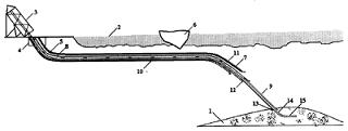
To deal with these issues, engineers created underground directional drilling technology. As shown in Figure 1, this technology includes the use of a "distant face." The directionally drilled space connects the day surface with distant underground face – the location of the construction activity.
Russian Patent # 2,295,024 | |||||
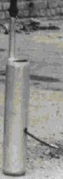
The authors started developing directional drilling technologies for underground construction from developing technology and equipment to install different types of markers in underground layers of soil strata through a wall of vertical borings. (See Figure 2.) This led to the development of a device that can be inserted in a vertical tube; the curvilinear tube is strengthened. Such markers can contain a radioactive source with a short lifespan, an electromagnetic marker or even the simplest marker available – emptiness or, in other words, void space.
Left: Russian Patent #1,818,494; Right: Courtesy of Abram Teplitskiy | |||||
We started developing devices for the curvilinear insertion of radioactive markers in different depths in soil strata to investigate three-dimensional soil movements in different technological situations and during different technological processes. To insert a radioactive marker in the soil through the wall of a bore hole, especially under existing structures, is not easy. Such an installation device has to move vertically, then turn and move horizontally under existing structure. In the 1970s, we developed a family of such devices for insertion different markers and gages to measure density, moisture content, permeability of soils, and other geo-technical characteristics of strata. By using the segmentation principle, we divided an insertion rod into independent segments. To operate these segments, we connected them by pivots and used pawls to hold the segments rigidly in the chosen direction. The inserting device can be plunged in the bore hole through a directional element, which can be installed on required inclination. The device could then be inserted into the soil by applying force to the system of pivotally connected segments. (The segments should be additionally clamped to each other to provide the necessarily rigidity and stability.)
TRIZ provides another unique approach for advancing technical systems, based on envisioning an ideal solution, identifying contradictions between the ideal solution and real conditions, and finding resources in a system to resolve these contradictions. We start with this path of problem solving by examining how to test soil under the foundations of buildings. Figure 1 shows a foundation with some structures; imagine that the builders needed to investigate the geo-technical properties of the soil under the foundation.
This is a complicated engineering task. The ideal solution is to get under the foundation from outside the building area. The ideal device could perform the following operations: be inserted vertically in the soil up to the depth of interest, then turn and finally continue inserting horizontally. For solving other problems the ideal device could turn once more and continue a second step of vertical (or at any other direction) insertion, etc. Such a device would be a compound of chain elements, connected pivotally and have a second controllable connection between elements. While making the first vertical insertion, all the connectors are inserted. The chain is rigid, so that the device can be inserted to the necessary depth. Then the controllable chain connectors should be sequentially extracted from the chain elements during a continuous insertion. After completing the turn, it would be inserted back in the chain elements for facilitating the horizontal part of the inserting route under the structure. A measuring device would be at the end of this compound of chain elements. A simple example of such a connection-disconnection device is shown in Figure 3.
Left: Inserting a probe horizontally under foundation; Right: Clamp-connector for chain elements | |||||
Rigid chain elements are connected pivotally and placed in a bended pipe, which provides a change from vertical to horizontal movement. Each element of a chain also has a second controllable connector with neighboring element. Figure 3 (right) shows a button-like controllable connector that can be pressed inside the hole with pressure placed on the directional tube's wall. When moving in the opposite direction, the button-like connectors are extracted from the neighboring chain elements, bringing flexibility to the chain elements. When this button is "closed," two neighboring pieces of a chain became rigid. We need only a mechanism that can extract button-like connectors and press them back after a task is completed. This example shows the resolution of the "rigidity-flexibility" contradiction by separating contradictory features in time. (Besides foundations, curvilinear elements also can be used for anchoring retaining walls. Anchors can be made as a flexible metal belt and bend like a loop, with a screw surface, cylindrical surface, or even a surface like Mobius strip.)
Besides installing horizontal drainage from vertical borings, a curvilinear approach can be used for ray-like drainage systems. These would contain horizontal drainage lines installed from the cylindrical wells along and/or under structures in need of drainage protection: big dams, embankments, depositories of ore tailings, etc. We needed a new approach to connect neighboring wet wells that reduced the number of pumping stations. After the wet wells were erected, we drilled a curvilinear boring beginning at the bottom of the wet well to the dry surface. To accomplish this task, the drainage tube was connected to a self-propelled pneumatic machine, called a pnevmoproboinik, with inclining wings. When the pnevmoproboinik moves, it follows a curvilinear trajectory on its way to the surface. Another pnevmoproboinik came to the surface from another wet well. At the surface, the ends of these two steel cables were connected and used to saw through the tract of soil between the surface of the soil massive and the bottom of the wet wells. Finally, the horizontal segment between the wet wells can be connected by a flexible tube. As a result, the two wet wells become hydraulically connected and water can be pumped out of these two wet wells with only one pump.
SU Patent # 1,488,399 | |||||
How can you repair a pipeline from inside a manhole? Picture a deteriorated elastic pipe underground. How can we move this pipe inside a host pipe, while simultaneously gluing it to the internal surface of the pipeline under restoration? We need to insert another tubular element inside the first one to restore the ability of pipeline to carry through any liquid substance. We can start to do this from any end of the old pipeline, but we need to install the new element over and ahead of already laid elements. This is a new type of contradiction – between monolithic (already laid element of a new pipe) and non-monolithic (before becoming a part of pipeline). One way to solve this contradiction is through the use of a spatial resource – wind a spiral strip over and ahead of the monolithic part of the existing pipeline. But we developed a more effective method, which used another spatial resource – using inverted pipes, or the other side of the tube, as shown in Figure 5.
RU Patent # 2,107,216 | |||||
The inverted-based method is based on the insertion of a hosepipe (6) made from elastic fibrous material inside the host pipe. The hosepipe is soaked by an impregnable polymer material. A flexible polymer hose inverts and advances in the host pipe, pressed to the inside surface through the pressure of fluid, subsequently setting and polymerizing. The inverting, the advancing of the hose, and its unfolding and pressing to the internal surface of the host pipe are all accomplished by using air pressure and the pressure of a water stand.
Now we will look at solving a technical contradiction by a division in time. How can we install drainage material in old pipelines without digging trenches? On one chemical plant, the level of groundwater raised and started to destabilize the foundation system. Experts recommended implementing permanent underground drainage. One proposal was adopted as highly cost-effective – use old deteriorated pipelines as the basis for a new drainage system. The entrance to the old pipelines could be from manholes, so only one problem remains – how to place sorted granular filter material in the prolonged underground pipeline keeping the construction works stable. Using TRIZ, specialists postulated an ideal final result – the filter material has to become drainage by itself, after being inserted in old pipeline. The contradiction in this case is as follows: filtered, sorted material during insertion has to be monolithic to provide smooth insertion. After insertion, the filter material has to be granular to ensure the drainage needs of a new structure.
After formulating this contradiction, we arrived at the solution: sorting the granular material in order, forming cylindrical blocks, filling them with water and then freezing them. The frozen blocks will have mechanical strength and are easily inserted in the pipeline. The cylindrical shape of blocks guarantees the quality of their connections in the old pipeline. Over time the ice will melt and the granular filling of the pipeline will serve as perfect drainage. (See Figure 6.)
SU Patent # 1,444,470 | |||||
To improve the quality of drainage, we suggested the installation of a compressed metal spring during the freezing of the drainage block. The drainage blocks will melt over time and the drainage will work as complete line. The process of installing the drainage is separated by time from when it will start to work by the time of ice.
Sometimes it is necessary to change destroyed pipelines and lay down new ones. For this purpose, it is necessary to have flexible tools – in this case, using a flexible cumulative cord, as shown in Figure 7.
Courtesy of Igor Endovtsev | |||||
A number of cumulative cords are strengthened by fastening elements with a non-permeable material. The diameter and length of this sleeve of cords corresponds to the internal diameter and length of the pipe to be destroyed. Fastening elements are secured along an optimal distance to the pipe's wall. One end of the sleeve is closed. The open side of the sleeve is fastened along the pipe's perimeter. An air camera, inside which is a folded sleeve with strengthening cords, also adds to the overall strength. After a supply of air enters in the air camera, the sleeve stretches and adjoins to the pipe walls. After the sleeves are stretched along the complete length of the length of pipe to be destroyed, the cumulative cord undermines the pipe's strength and, as a result, is destroyed.
Using the contradiction matrix, and singling out various contradictions at the root of each problem, leads to a number of possible, inventive and ideal solutions for the problem at hand –even when it comes to drilling underground.
Roustem Kourmaev is a well-known civil engineer and interationally-known businessman from the Russian Federation. Contact Roustem Kourmaev at tepl (at) sbcglobal.net.
Mikhail Makariev is a technical director of KRUS in Ufa, Bashkiria. Contact Mikhail Makariev at tepl (at) sbcglobal.net.
Abram Teplitskiy, Ph.D., is a consultant for inventing, applied physics and civil engineering. Contact Abram Teplitskiy at tepl (at) sbcglobal.net.